The meaning to draw to scale. While learning about architecture, I remember needing to overcome many stumbling blocks, in particular those surrounding fundamental questions about what makes good design. Included in this larger inquiry was the ability to think spatially, the confidence to translate ideas into space, and how to sketch in an iterative manner.
Both the questions and the answers became evident after guidance from dedicated mentors, personal design skill development, and actual professional experience as both an intern and, later, conducting projects on my own. And yet, one of the most challenging notions that took time to understand was the issue of scale: what makes for appropriate scale of a space or a building? While the question may seem simple, the answer was more complex than expected.

To work at scale
To work “at scale” in any architectural project means that one develops a scheme at a scale other than full scale or life size. In Europe, where I received my training, we worked in metric, typically at scales of 1/500; 1/200; 1/100; 1/50 and 1/20. This meant that for 1/500, one centimeter in the drawing or model equaled 500 meters in real life. When arriving in the United States to further my studies, abstract meters were replaced by a customary system of measurements called the foot.
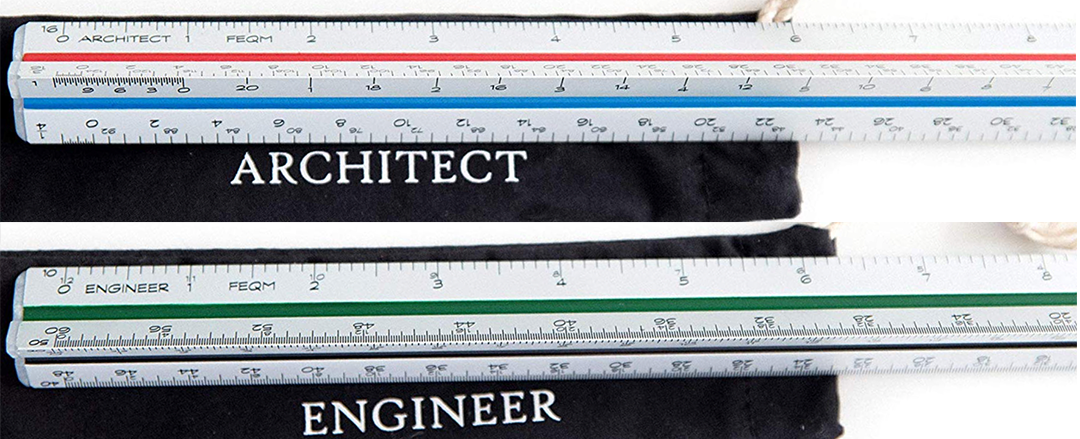
Lo and behold, in addition to this shift in scale and most importantly envisioning space in feet rather than in meters, I discovered that a foot could be divided into 12 equal units called inches (architectural scale), or into 10 equals units (engineering scale).Imagine what a mess when I grabbed any available scale on my desk to only find out that there was this subtle but fundamental difference.
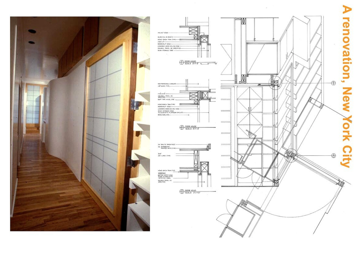
Finally, with the architectural scale in hand, I learned that most architectural projects in the US are designed at scales of 1/32; 1/16; 1/8; 1/4 and 1/2. (As with metric scale the relationship is between the unit of design compared to the unit in reality, for example 1/32 means one inch on the page equals 32 feet in reality; 1/32″=1′-0″.) When working on my first projects in NYC, I even ventured to design cabinets at 1-½” scale, which I had learned was appropriate for Shop Drawings (see above and last drawings).
To understand scale
After having mastered this first notion of drawing to scale, was to understand what it meant for a room to be at scale, to have a scale. One day, a professor asked about the scale of a room in my design, and in particular the entrance to the room. The answer seemed self-evident, and I was delighted to explain that I was designing the project at 1/50 scale. My answer seemed to have little resonance, prompting her to repeat the question. I thought about it and, with confidence, again answered that the door opening to the room was 90 centimeters wide (a typical door width in Europe), thus my room had the stated dimension and desirable proportions. I even pointed to nearby stairs to confirm that they were correctly dimensioned, thus showing that the plan was at scale 1/50.
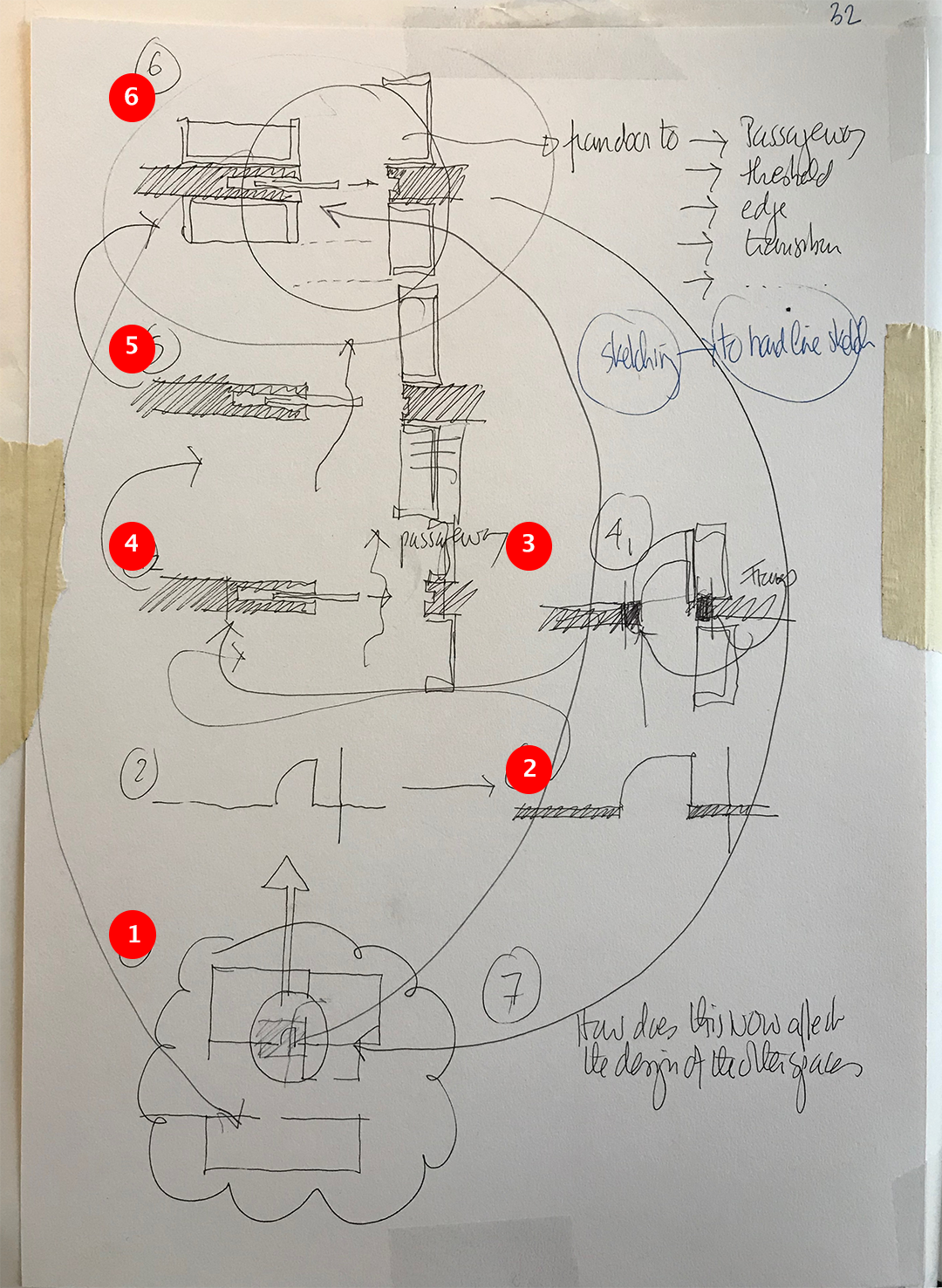
My answer was again not what my professor had in mind and she shared the following thoughts. While I was correct in my assumption in designing at scale the basic components of my plan, my entrance lacked scale for its usage, based on the particular function of that room and overall assigned program (thesis and poetry) envisioned for my building. To retrace that memorable discussion, many years later, I devised for my students six basic sketches based on how one enters a room (i.e., bedroom) and the need to include various information that suggest an understanding of scale. (I like ideas of domesticity through renovation projects for their quality of being both architecture and interior architecture.)
An example with 6 points

The above sketches (1 – 6) not only explore this notion of working at a particular scale AND giving scale to a drawing, but more importantly, they further suggest a process of defining the difference between the functional necessity of a door and the architectural manifestation as an edge, a threshold, a transition, limit, or passageway. In other words, how to make a spatial event out of such a mundane moment of going from one space, or room, to another, and how this exploration carries fundamental questions of scale. The sketches below are drawn in plan but certainly deserve a further three-dimensional study in section, elevation and even in axonometric. However, as I learned, I can draw in plan while understanding the three dimensional repercussions of my drawings.
Sketch 1 shows diagrammatically a detail of an entrance to a room from a corridor with access to the right to an adjacent bathroom. The drawing has no scale at this time (possibly 1/32=1′-0″), just a basic idea AT SCALE given the relationship of spaces to each other. The lines here are solely the expression of the thickness of the lead.
Sketch 2 illustrates at scale (~1/16=1′-0″) a partition wall, including a door and the directionl swing of opening. Here the wall gains thickness rendered in black hashed lines (called poche). At this scale, I tend to poché the wall or any structural elements as that clearly defines what is space (the emptiness) versus what defines the space (i.e., wall). The term poché (a term that indicates the inhabited space of a wall or column and is either represented filled or cross-hatched) is one of those words used by architects to give readability to their drawings.
Coined by the French Ecole des Beaux-Arts, an educational system that trained architects in a formal setting, the term is given to emphasize any element that defines space such as structure, non-loading bearing partitions and even, at times, built-in furniture. Its purpose is also to understand the shape of those defining elements and how they impact the overall quality of the space.
Sketch 3 is similar to sketch 2 but now includes some detailing showing the door’s frame and the thickness of the door. This level of detailing can be equated to a scaled drawing at ~1/8=1′-0″. It is still basic in its constructive expression and if the wall does not contain any specifics, I learned that for a general contractor bidding on a job, it is preferable to not indicate any specific construction methods in how to build the wall. Here the door does not indicate any architectural treatment that deserves the notion of passageway, transition or threshold as described above.
Sketch 4/5/6 are more robust and may be equated to a scaled drawing at 1/4=1’0″ or at a larger scale that would demand to be drawn at scale 1 1/2=1’0″. Here the architectural idea is to move from a simple wall with a door (previous iterations), to a spatial thickness containing cabinets on either side of the door (which now miraculously is a sliding door!) offering new spatial possibilities.
In residential projects, I favor incorporating as much storage, in particular when working on urban renovations where space is limited and the square footage expensive. The sketches are now more than an idea, and when further worked out, detailing would bring the concept to the level of construction drawings. Each advancement in scale leads to more detail both in construction and in concept, and of course to be resolve at a more appropriate scale, closer to 1:1. These sketches of a door and its opening, grow into a spatial moment that, for me, start to be inhabited by cabinet work and no longer rely simply of a door.
Conclusion
The sketches below are a modified synopsis of the above sketches and show the development leading to the plan below (detail of entrance sequence) and eventual construction drawings for the completed Abraham renovation in NYC.


