Study sketch to drafted sketch. Sketching might be for some a natural gift, but for most of us it is about the patient—and often painful—practice of setting one’s pencil on a white sheet of paper and letting ideas leave their mark.
As skills are honed by coordinating mind, hand and pencil, sketching as a process of iteration, becomes second nature. Eventually, those free-hand sketches become measured plans and sections, thus requiring more formality. Prior to drafting them precisely (either mechanically by hand or digitally), I favor a transitional method where one drafts in sketch form, which I call a drafted-sketch. What does this mean and how does one draw them?
Conceptual diagram
First, in the process to create a draft-sketch, it is important that in following a succession of iterative drawings, one identifies the most pertinent sketch and “saves” it by diagraming the essential, or fundamental concept behind the sketch. This will allow any progression to be conceptualized and act as a milestone in the design process. Each concept should outline graphically the major components (i.e., spatially, formally, functionally, structurally) that are essential at the time of the conceptual diagram.
This process is key to moving from sketching to a draft-sketch, which may be expressed either in plan or in section. Of course, one can proceed similarly in other orthographic projections (axonometric and isometric), or perspectival drawings, but for this blog content, we will rely on plans.
It is also important to note that here we are discussing sketches and conceptual diagrams drawn geometrically and NOT mathematically. This means that the drawings are concerned with shape, size, and their relative position to each other with a constant eye on the proportional properties of the spaces that are suggested in the drawing. If drawn mathematically, the sketches would include all of the above, in addition to precise measurements of the spaces and other important features.Image 1: author’s initial conceptual sketches (author’s collection)
Author’s example
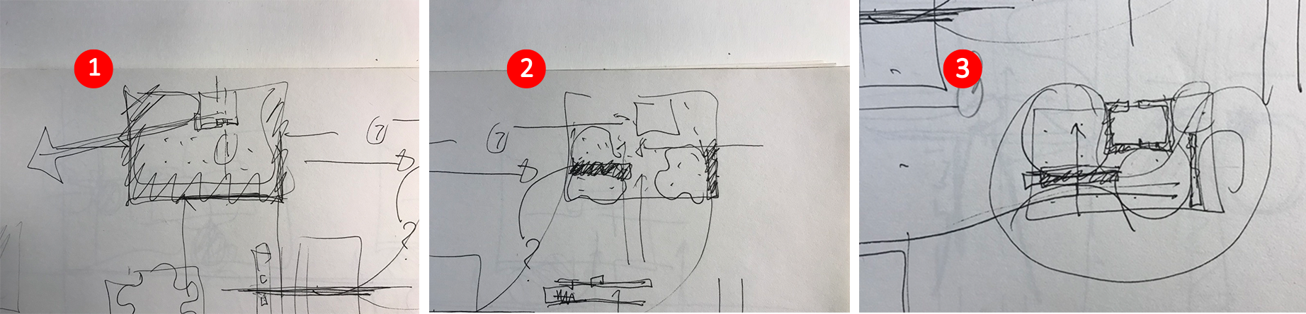
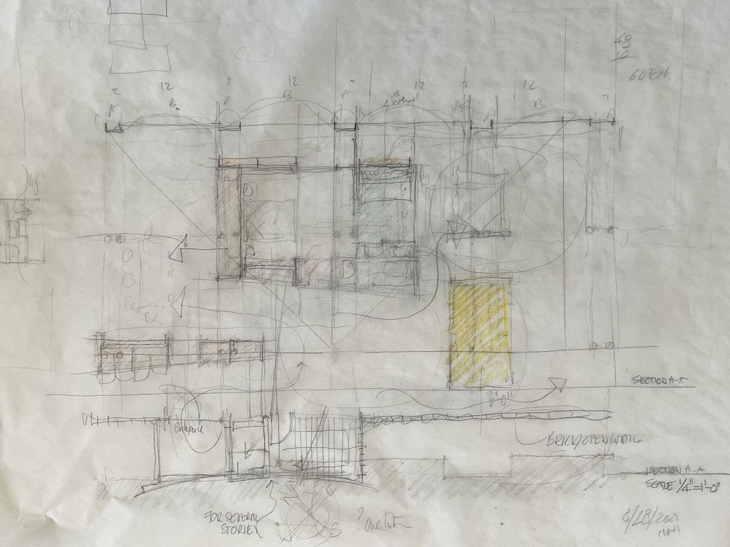
The black and white images here show three different conceptual stages as described above. In these examples, the idea (program or thesis) was to work on a simple one-story house by creating free flowing spaces versus a series of rooms to accommodate most domestic functions. No particular site was considered, yet orientation and views assisted in the overall organization of the parti (diagram based on the organization of functions).
The first image (1.1)

Develops a boundary of the house illustrated in loose hashed lines. At the top of the drawing one finds an enclosed square space. The scattered dots suggest spatial continuity throughout the plan.
The second image (1.2)

Maintains the overall rectangular shape of the house, as well as the enclosed square/room. Three blobs indicate spatial areas with the following functions: entrance, living, and dining. At this point, the assumption is that the enclosed room (square) serves as a bedroom, thus the closed shape denotes privacy. Added to this drawing are two darkened rectangles. The far left one indicates a galley kitchen in the form of an elongated piece of furniture next to the entrance. The second rectangle ends the right-hand side of the house and, at this stage of the design, contains storage for a living room/office area as well as serving as a structural wall. Finally, the assumption is that the entire house has a columnar structure.
The third image (1.3)
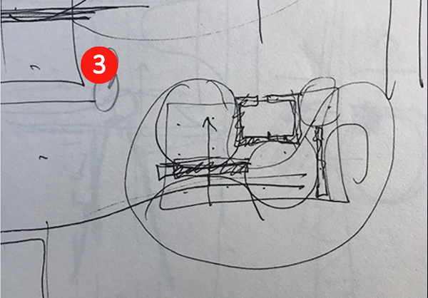
Is almost identical to the second diagram with the exception that the three blobs are now defined by circles that outline all left-over spaces (areas) after the two rectangles and enclosed room are correctly positioned. The bedroom has now gained thickness rather than being expressed by a simple line, and the right-hand rectangle has migrated slightly towards the interior of the house. This thickness, as we will see in image 2, will become a linear closet in lieu of a typical non-load bearing partition.
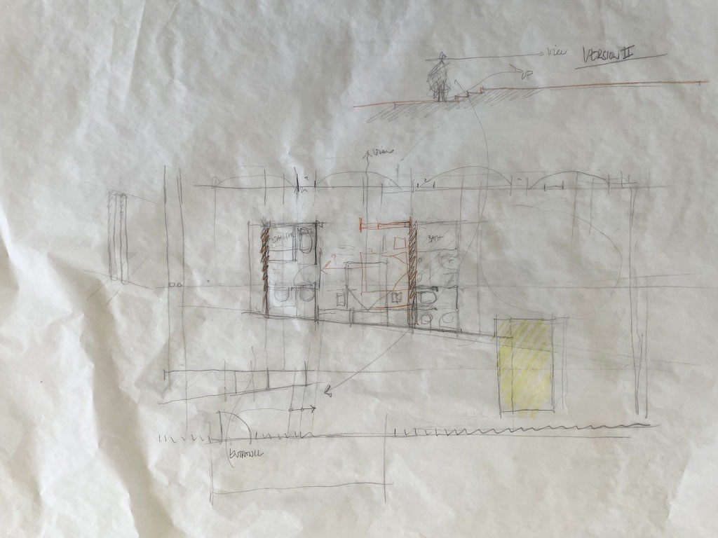
Final author’s sketch prior to a drafted-sketch
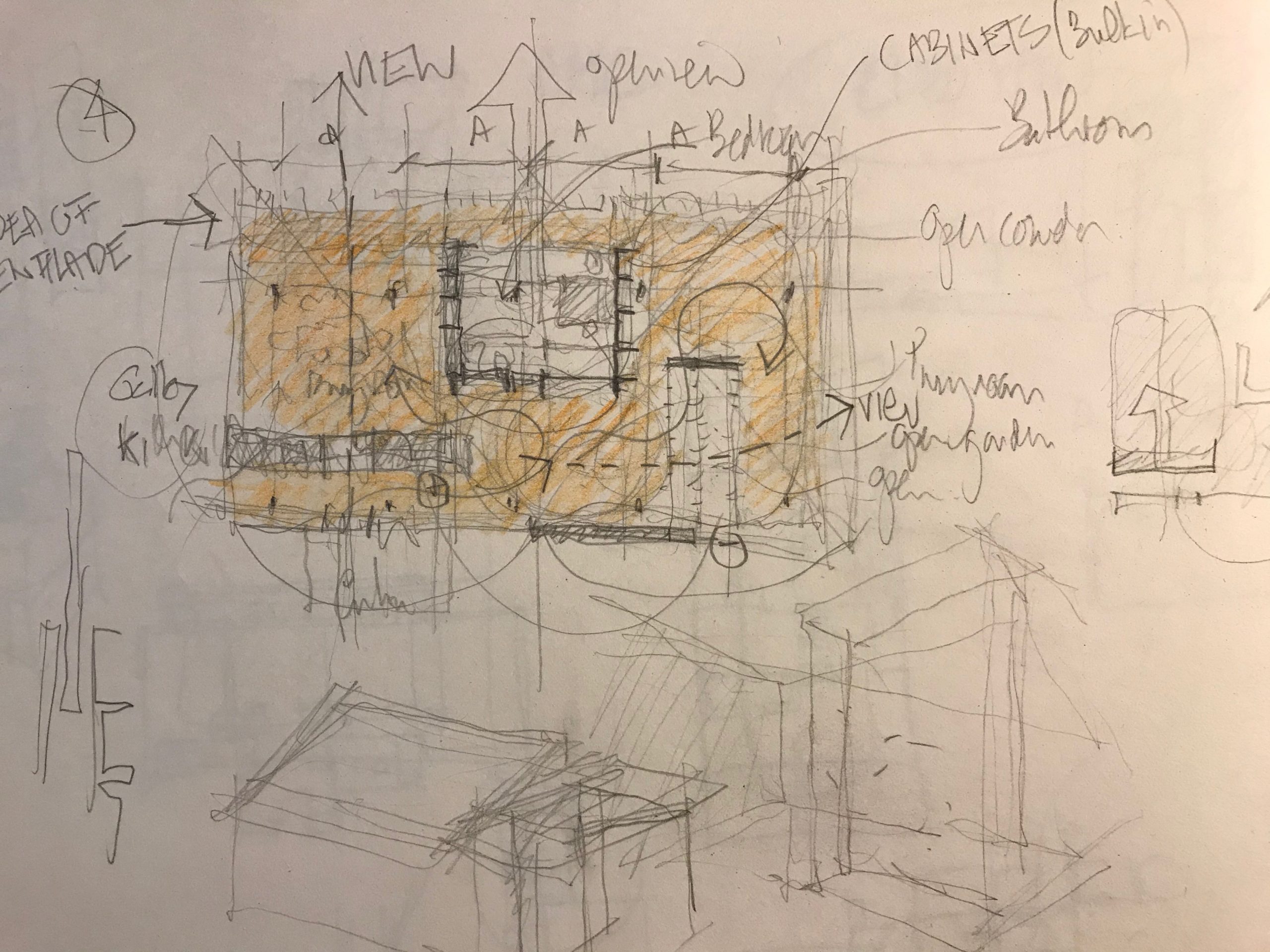
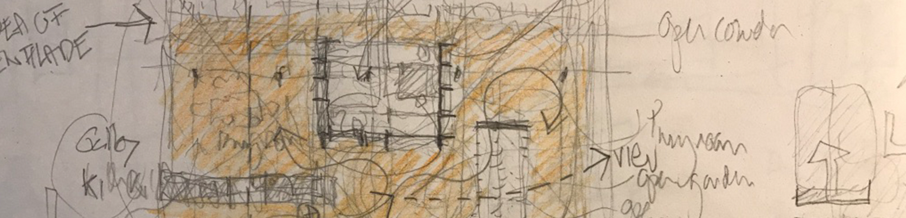
The above free-hand colored diagram (last one in this series (1.1; 1.2; 1.3, and which is less conceptual as the first three diagrams) represents further clarification of the previous three sketches by emphasizing the load bearing columnar structure and their proportional spacing (A-A-A-A); the galley kitchen has now an opening allowing a view through the cabinets from the entrance towards the dining area (in fact offering a perspectival view through the entire width of the building which is expressed by the long arrow ending up with the word VIEW); the enclosed bedroom is spacious and defined at its periphery by various pieces of furniture that both serve the bedroom, bathroom, and adjacent spaces.
Opposite the bedroom’s bathroom, the bedroom is open in its entire width to the garden (large arrow) and ties perpendicular to a long corridor similar to a traditional enfilade where rooms are formally aligned with each other. In this example, the back corridor joins the dining area (left), the bedroom (middle) and the secondary living room/guest-room, with a fold out bed (right).
The living room is directly to the right of the entrance and through a chicane (serpentine curve) expands to the right as a reversed L shape space that contains an informal living area/guest-room with an adjacent office space. The most important move in this sketch is how the second rectangle now becomes an enclosed interior garden/patio allowing views from the living room to the office space while bringing additional light within the house.
Finally, it is important to note that the overall plan is formed by two identical squares (never truly conceived as such but simply as a natural evolution of the design). The drawing remains a geometrical drawing and not a mathematical one, it does not yet have a scale (it is double or triple the size of the previous three sketches), yet, all spatial elements are to scale and proportioned to each other.
Author’s initial drafted-sketches
Student’s sketch
This sketching process was further explored within an academic context. Students in my second-year design studio were encouraged with a similar brief—a house with basic functional requirements—to sketch their ideas, to conceptualize them diagrammatically, and then to draft-sketch them before drafting them to further their projects.

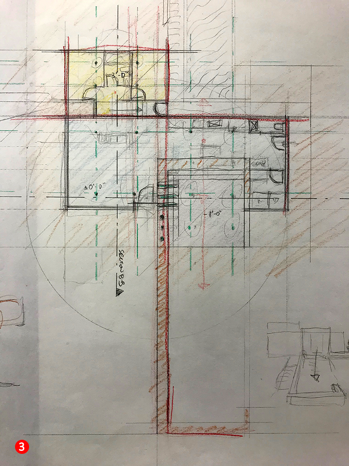
While this last phase is absent in my own examples (drafted plan versus sketch-draft), I found the student images (below), to be pertinent enough to highlight efforts regarding drawing in the form of draft-sketches. In fact, it is this particular student who approached me with the question as of how to proceed further, when sketching seemed to be “exhausted,” thus requiring more formalized drafted plans and sections. Image 4: Second year student’s first conceptual sketches -idea and seeking proportional systems (author’s collection)
To contextualize the final process of drawing a draft-sketch, I have included two of this student’s conceptual diagrams in sketch form (above) as a background to his four sketch-drafts featured below.
- Sketch 1 (above 4.1) illustrates in plan the overall spatial organization of the house with a focus on a centralized dining space to the right of an existing C shaped foundation wall. Proportions, a columnar structure, and some basic ideas of how to organize spatially the functions, are represented here in a clear diagrammatic manner.
- Sketch 2 (above 4.2) displays a strong geometrical system underlying the design features found in Sketch 1. This system equates proportion with an underlying order that supports the need to move to the draft-sketch.

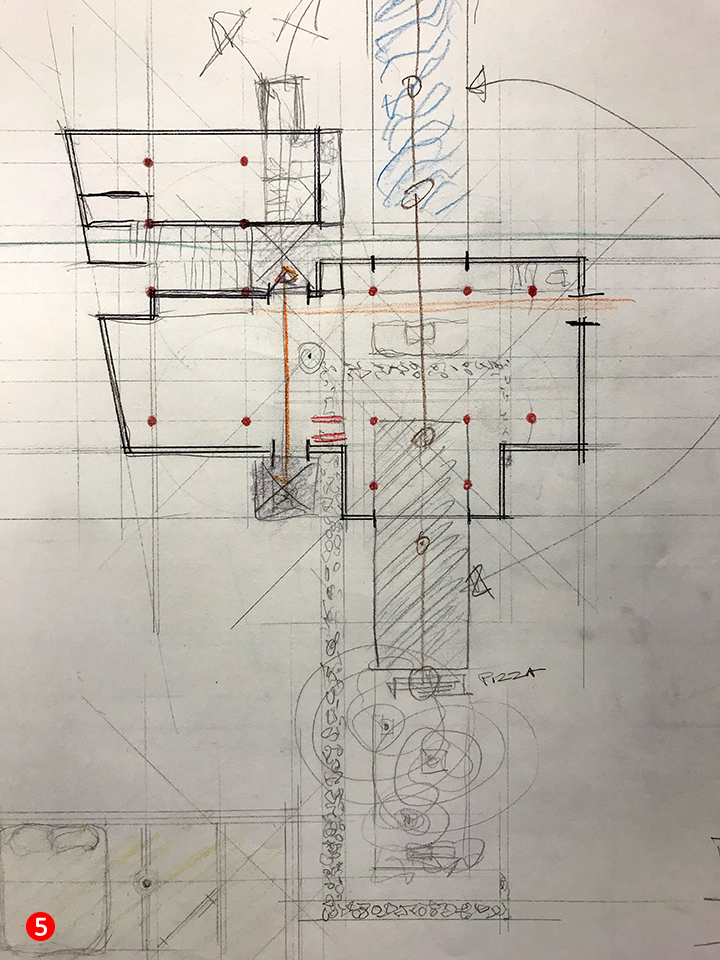
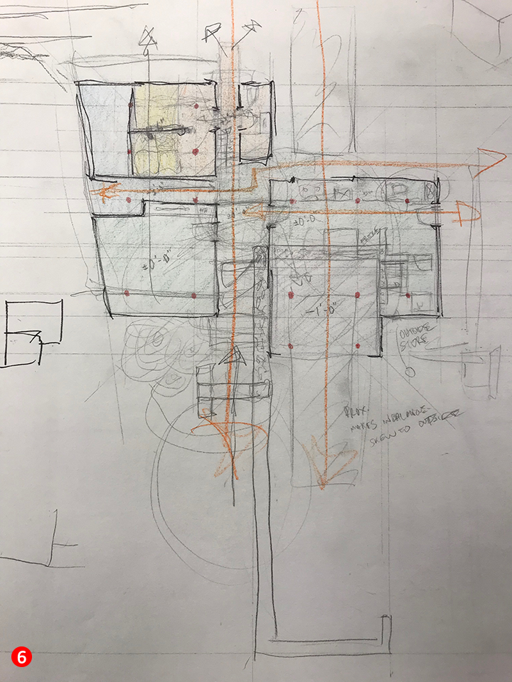
Student’s four draft-sketches
This following four draft-sketch plans (Image 5, above 3-6) illustrate the superimposition of the above two sketches (1 and 2) by using mechanical drawing techniques and a mathematical approach to measuring spaces more precisely. This allows the drawings to gain more formality by interpreting the initial two concepts. In each of the four drawings, one clearly sees various underlying construction lines that assist the student to position all of the required spaces which can now be adjusted based on more precise and measurable dimensions. The introduction of color defines zones for day and night (public versus private), and other color accents indicate structure or items of importance.
What is critical in this process, is to take the conceptual diagram (Sketch 3.1 and 3.2) as a spatial outline on which the student can now sketch upon (3.3 – 3.6). Adjustments, interpretations, conceptual changes are made freely through sketching while maintaining clarity of the overall concept. The superimposition on a drafted sketched-out plan with a loose sketching technique offers great potential to continue to test ideas while being both precise and playful in one’s discoveries and intentions. The notion of precision and calibration of design thinking takes another meaning and can (must) be done prior to drafting a plan!

In conclusion
A drawing by the same student that shows where the next stage of the project may go; the first drafted drawing.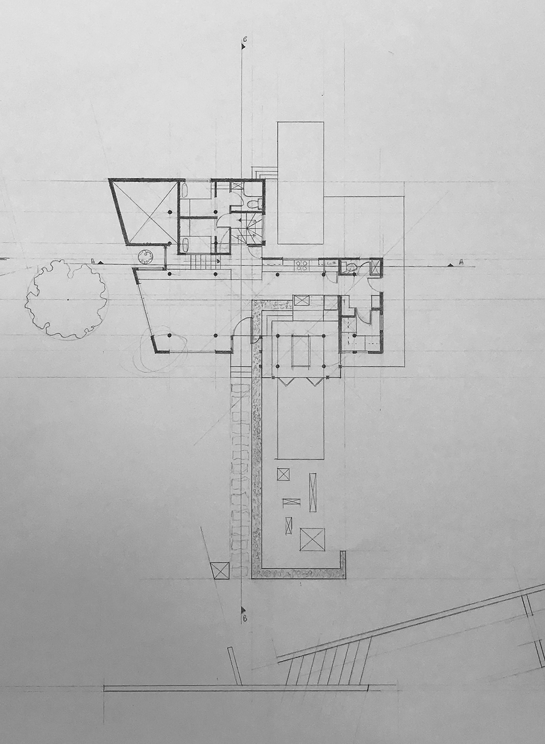
Image 10: identical student as above; first AND final drafted plan proposal based on all previous conceptual sketches and draft-sketches (see above images 6-9). Author’s collection
Architectural Education: about sketching -an iterative process. Part 1
Architectural Education: about sketching -an iterative process. Part 2
Architectural Education: The nature of IDEAS