While rekindling an idea for one of the numerous designs of a courtyard house I am working on, I wanted to use a model sketching technique ( that involves folding paper to rapidly create an object in three dimensions.
For this technique, I would only use one large piece of Bristol paper with no glue; simply cutting, folding, and occasionally taping. Over the years, I have introduced this process to my students both at the undergraduate and graduate levels with, I will admit, somewhat mixed results.
The mixed results are not due to a lack of complexity or richness in the exercise; it is because students often have difficulty thinking holistically about their building (i.e. as in seeing their concept as a totality and not a series of fragments), especially when it comes to defining volumetric qualities that include the expression of facades often designed at the last moment. Of course, the traditional making of small mass models out of plasticine has its virtues and allows students to rapidly see how a building looks, in addition to establishing a principle of settlement to anchor the project as site specific.
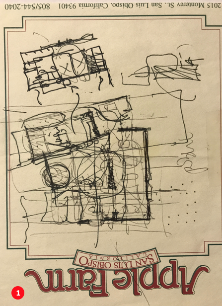
With a series of sketches at hand, dating as far back as 2006 (Image 1 below, that reminds me that I did it during my interview to secure the position of department head at Cal Poly. At that time, I was thinking of building a house there…), I wanted to understand the students’ difficulties. Although I have explored the folding technique previously in a blog, I wanted to apply it to a project of mine at a different stage, namely the design of a courtyard house, and through this example, to further have the students re-examine the relationship between the making and the furtherance of the design.
Courtyard house
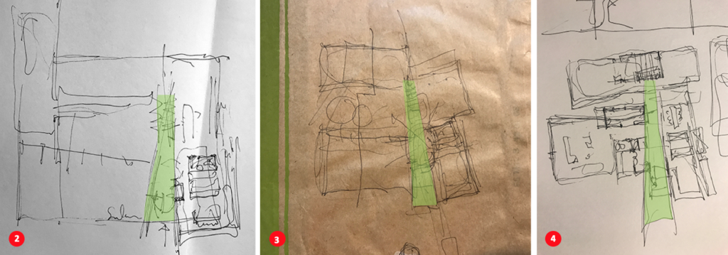
I looked to a series of eight iterative drawings that span over a decade of thinking to display an overall design strategy (Images 1 and 2 above, and 4 and 5 below). Looking at the sketches side-by-side, it became clear that each plan was based on a functional organization of the house around a single courtyard, working with either an L shape or a U parti as a unifying geometry (Image 3 below).

Within this self-imposed constraint, a wedge-shaped strategy serves as the overall functional distribution of the house. This triangulated space is constant in each of the sketches, to the exception of numbers one and six (see red dots and numbers in Images 1 and 4). The latter sketch (number 6) abandoned the wedge-shaped space, creating an unnecessary and incongruous functional distribution in the house.
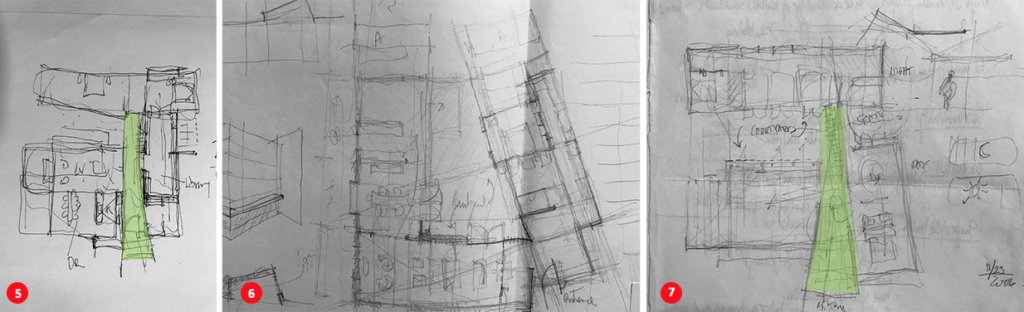
In the last sketch of the series (Image 5 below), the elongated pie-shaped space reconfirms its role as the primary element of distribution of the house which is comprised of a main entrance and foyer; extension to the living room with a visual connection to the kitchen and dining rooms; and courtyard and patio, ending with a dual system of circulation.
This system of circulation has a ramp (on the left) that leads to a lower level that includes a stepped library (that reaches to the second-floor studio), master bedroom, guest bedroom and a gentle stair (on the right) leading to a second-floor guest bedroom. Realizing that this multifunctional ‘corridor’ (the wedge) serves as an umbilical cord for the entire distribution of the house, I thought that there must be a way to express this idea in model form, and not simply in plan and section.

Sketch-models
It was at this point that I embarked on making a series of conceptual models for the courtyard house. The idea was that if the wedge-like space in plan was essential to the overall functional and spatial layout of the house, it could also be expressed volumetrically.
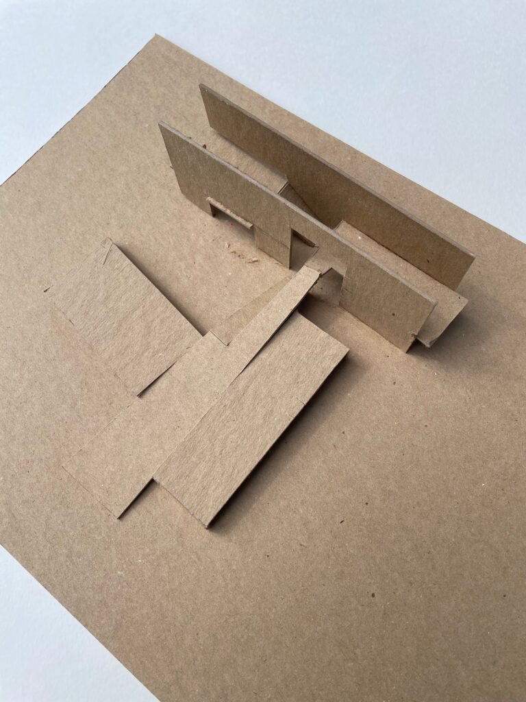
My first attempt (Image 6 above), isolated the wedge to understand its potential. A rapidly built chipboard model served the purpose, but was made of several pieces, thus it lacked the conceptual coherence that I had imagined spatially. The desired continuity expressed in plan was lost or was not even expressed.

In a second iteration (Image 7 above), I wanted to focus on how the wedge-shaped corridor helped create the adjacent volumes which were central to the design. Moving to Bristol paper, which allowed me to fabricate the model rapidly with a few cuts and mostly folds to give structural stability, I was able to regain the idea of the wedge but still missed developing the volumes. Yet, the entire floor was made out of one single piece of paper, which was already a tiny victory.

In the last iteration (Images 8 and 9 above and below), where the volumes needed to support the internal organization of the corridor, I was also interested in finding out if the entire model could be completed using a single sheet of Bristol paper. After much trial and error, and a little tape, I was able to make an entire model where each move and volume informed the other; and this by expressing a seamless continuity between floors, walls, circulation, openings, and roofs.
The final sketch model and accompanying drawing (Image 10 below) show two very different realities, but nevertheless the same desire to understand the project three dimensionally while never losing sight of the important wedge-shaped space, which is the parti, or the thesis at the functional level.
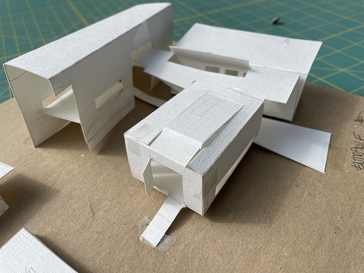
The model may seem clumsy in its proportions and generic suggestions of vertical and roof openings. There is no refinement at this time (no need) that could point toward important information that other model techniques could showcase or that digital models could easily capture.
However, the success of this model lies on another level. One that embraces a hands-on design making, a constant visual calibration of one’s intuition, an infinite sense of playfulness and experimentation; all resulting in forgoing any preconceived inhibitions about what a house should look like. The rapidity of this technique capitalizes on accidents between the coordination of mind and hand, always ready to take advantage of the model’s suggestions.
Epilogue
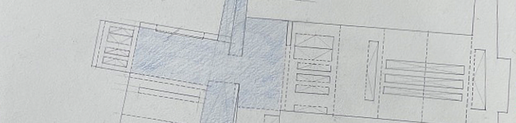
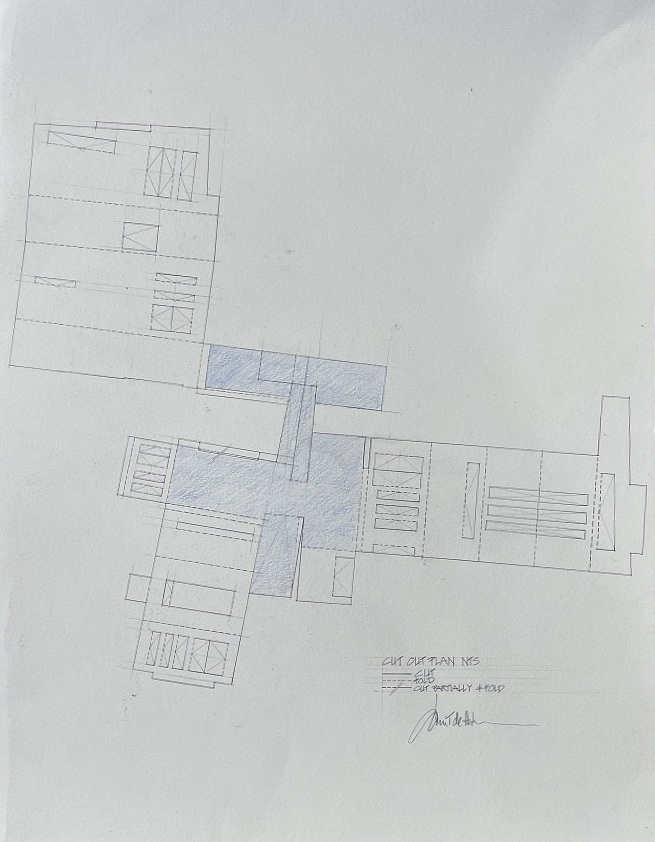
While the as-built final model suggests a seamless continuity between folding, cutting, and occasionally taping, it failed to have the discipline of creating a model out of one single piece of paper. I returned to the drawing board (Image 10 below) to produce a pattern that could create the model that I had in front of me. The drawing shows in blue the footprint of the wedge with its functional tentacles reaching out to adjacent rooms (very similar to image 7, above), while the floors, walls, and ceiling/roofs are spatially continuous. One important lesson is that I no longer can conceive of a wall as solely an element existing between two horizontal surfaces (floor and ceiling/roof). Abandoning a traditional reading opens up new ways of seeing the wall as an extension of either the floor or the ceiling—an in-between condition—thus I favor this technique as a seamless design tool that sees spatial continuity in a three-dimensional reality, but does not replace a more traditional approach through plans and sections.
Additional blogs of interest
Architectural sketching and how do I sketch
The importance of sketching for architects, Part 1
Some thoughts on sketching by hand
Sketching on a field trip, Part 1
Sketching on a field trip, Part 2
Issues about sketching, Part 1
Sketching -an iterative process, Part 2
Sketching -an iterative process, Part 1
Architectural Education: What issues does one encounter when sketching?
Why Model Sketching? Part 5
Why Model Sketching? Part 4
Why Model Sketching? Part 3
Why Model Sketching? Part 2
Why Model Sketching? Part 1